

Category :Electric control valve
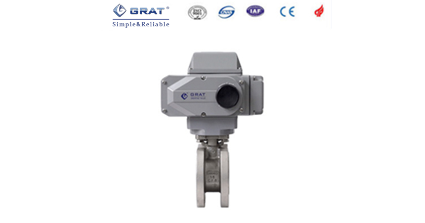
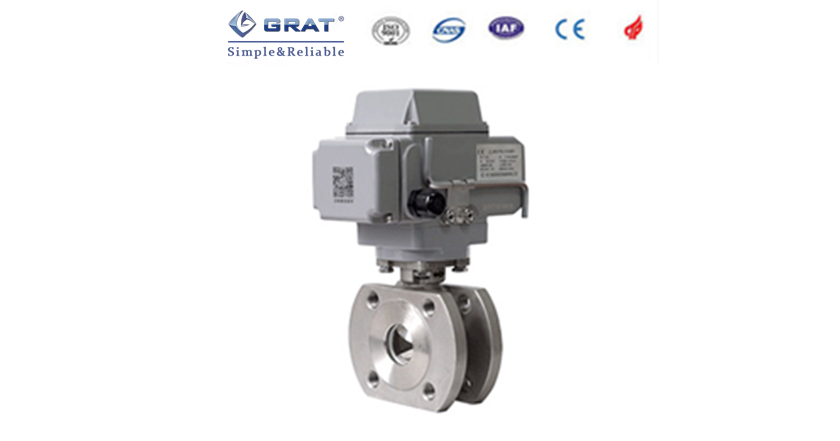
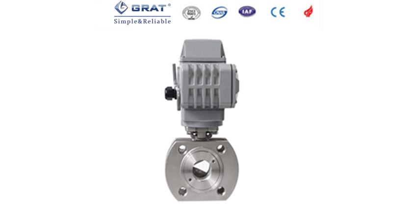
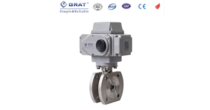
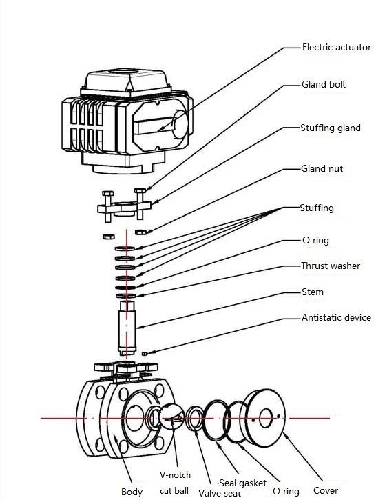
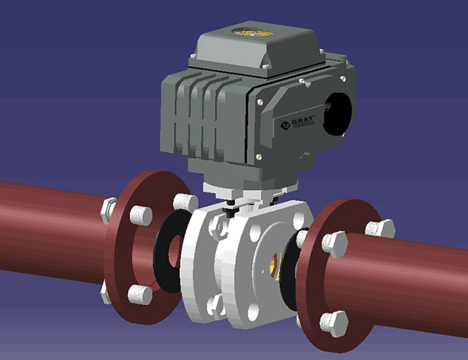
Product Name: Electric V-notch Cut Control Valve
Product introduction:
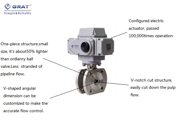
Electric V-notch Cut control valve configured with the intelligent actuator which can make the proportional control receives the 4-20 MAC or 1-5 VDC signal from high precision electric actuators and indicates the angle of direct instruction and feedback. The switch type product can operate only by the single-phase power to make the parameters regulation including pressure flow temperature the level of liquid and so on.
*Accurate and repeatable position control and feedback signal using 4-20 mA signal withup to 0.3% accuracy
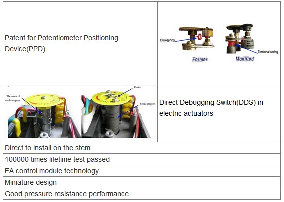
*More than 100000 times operation test passed without fault
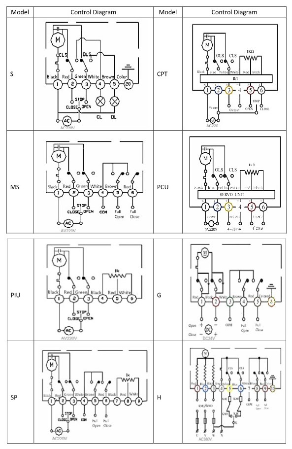
*Powered by 1-phase 3-phase or DC power supplies
*Digital communication options including HART® Mod-bus® available
*Permanently lubricated and maintenance free drive train
*Dust-proof and Watertight to IP67
*Self-recovery overheat protector
*Optional torque limiter/remote control/dehumidify heater
*Field selectable adjustments for :
Zero and span
Command signal type
Standard or reverse acting
Manual-auto operation
Output shaft position return on loss of signal
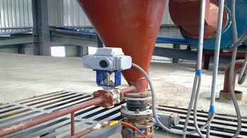
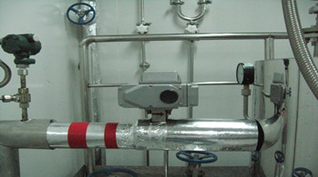
The V-notch cut in disc can rotate reversely & correspondingly with metal seal to produce shear force to cut off fibre and prevent the block. This valve is special suitable for mud and fibrous media and suspended solids containing minimal media.
|
Nominal diameter |
DN15-DN200(Please contact for bigger size) |
|||
|
Nominal pressure |
PN1.6MPa |
|||
|
Connection type |
Flange |
|||
|
Valve seat |
PTFE soft seal |
|||
|
Action time |
15s、30s(Optional)(0-90°) |
|||
|
Supply power
|
AC220V
|
AC380V
|
DC24V
|
|
|
Control signal |
4~20mA
|
0-5V
|
||
|
Output signal
|
4~20mA
|
0-5V
|
||
|
Fluid temp.
|
≤220℃
|
|||
|
Ambient temp.
|
≤50℃
|
|||
|
Suitable fluid
|
Food Grease Fibrous fluids Pulp Coral pulp Water Oil Gas
|
|||
|
Deadband
|
0.3%~3.0% Adjustable
|
|||
|
Body material
|
WCB
|
SS304
|
SS316
|
SS316L
|
|
Valve seat material
|
SS304
|
SS316
|
SS316L
|
|
|
Disc material
|
SS304
|
SS316
|
SS316L
|
|
CNS Standard size of Short flange
Design standard:GB/T12237-2007
Flange standard:GB/T9113-2010 Unit:(mm)
|
Nominal diameter |
d
|
D1
|
K
|
D
|
n-Md
|
f
|
L
|
H
|
W
|
|
|
DN15
|
1/2〃
|
15
|
45
|
65
|
95
|
4-M12
|
2
|
35
|
210
|
196
|
|
DN20
|
3/4〃
|
19
|
55
|
75
|
105
|
4-M12
|
2
|
38
|
216
|
196
|
|
DN25
|
1〃
|
25
|
65
|
85
|
115
|
4-M12
|
2
|
50
|
223
|
196
|
|
DN32
|
1-1/4〃
|
28
|
76
|
100
|
140
|
4-M12
|
2
|
50
|
230
|
196
|
|
DN40
|
1-1/2〃
|
38
|
83
|
110
|
148
|
4-M16
|
3
|
67
|
240
|
196
|
|
DN50
|
2〃
|
49
|
102
|
125
|
156
|
4-M16
|
3
|
72
|
250
|
196
|
|
DN65
|
2-1/2〃
|
64
|
120
|
145
|
185
|
4-M16
|
3
|
94
|
298
|
255
|
|
DN80
|
3〃
|
73
|
143
|
160
|
200
|
8-M16
|
3
|
120
|
312
|
255
|
|
DN100
|
4〃
|
90
|
168
|
180
|
220
|
8-M16
|
3
|
141
|
322
|
255
|
|
DN125
|
5〃
|
110
|
185
|
210
|
245
|
8-M16
|
3
|
165
|
397
|
255
|
|
DN150
|
6〃
|
145
|
208
|
240
|
277
|
8-M20
|
3
|
225
|
422
|
255
|
|
DN200
|
8〃
|
195
|
265
|
395
|
335
|
12-M20
|
3
|
275
|
512
|
255
|
DIN Standard size of Short flange
Design standard:DIN3375/1,2,EN12516-1
Flange standard:DIN EN1092-1 PN10-PN40 Unit:(mm)
|
Nominal diameter |
d
|
D1
|
K
|
D
|
n-Md
|
f
|
L
|
H
|
W
|
|
|
DN15
|
1/2〃
|
15
|
45
|
65
|
95
|
4-M12
|
2
|
44
|
220
|
196
|
|
DN20
|
3/4〃
|
20
|
58
|
75
|
105
|
4-M12
|
2
|
44
|
220
|
196
|
|
DN25
|
1〃
|
25
|
68
|
85
|
115
|
4-M12
|
2
|
50
|
223
|
196
|
|
DN32
|
1-1/4〃
|
32
|
78
|
100
|
140
|
4-M16
|
2
|
60
|
237
|
196
|
|
DN40
|
1-1/2〃
|
38
|
88
|
110
|
150
|
4-M16
|
3
|
65
|
244
|
196
|
|
DN50
|
2〃
|
49
|
102
|
125
|
165
|
4-M16
|
3
|
80
|
245
|
196
|
|
DN65
|
2-1/2〃
|
62
|
122
|
145
|
185
|
4-M16
|
3
|
110
|
306
|
255
|
|
DN80
|
3〃
|
74
|
138
|
160
|
200
|
8-M16
|
3
|
120
|
326
|
255
|
|
DN100
|
4〃
|
100
|
158
|
180
|
220
|
8-M16
|
3
|
152
|
338
|
255
|
|
DN125
|
5〃
|
118
|
188
|
210
|
250
|
8-M16
|
3
|
180
|
363
|
255
|
|
DN150
|
6〃
|
150
|
212
|
240
|
285
|
8-M20
|
3
|
232
|
396.5
|
255
|

CNS Standard size of long flange
Design standard:GB/T12237-2007
Flange standard:HG/T20592 Unit:(mm)
|
Nominal diameter
|
L
|
D
|
K
|
D1
|
n-Φd
|
b
|
i
|
H
|
W
|
|
|
mm
|
in
|
|||||||||
|
15
|
1/2″
|
130
|
95
|
65
|
45
|
4-14
|
14
|
2
|
209
|
196
|
|
20
|
3/4″
|
130
|
105
|
75
|
55
|
4-14
|
16
|
2
|
211
|
196
|
|
25
|
1″
|
142
|
113
|
85
|
65
|
4-14
|
18
|
2
|
218.5
|
196
|
|
32
|
1-1/4″
|
165
|
140
|
100
|
78
|
4-18
|
18
|
2
|
233
|
196
|
|
40
|
1-1/2″
|
165
|
150
|
110
|
85
|
4-18
|
18
|
2
|
234
|
196
|
|
50
|
2″
|
203
|
165
|
125
|
100
|
4-18
|
20
|
2
|
248
|
196
|
|
65
|
2-1/2″
|
222
|
185
|
145
|
120
|
8-18
|
20
|
2
|
294
|
255
|
|
80
|
3″
|
241
|
200
|
160
|
135
|
8-18
|
21
|
2
|
320
|
255
|
|
100
|
4″
|
305
|
220
|
180
|
155
|
8-18
|
22
|
2
|
339
|
255
|
|
125
|
5″
|
356
|
250
|
210
|
184
|
8-18
|
22
|
3
|
392
|
255
|
|
150
|
6″
|
394
|
285
|
240
|
210
|
8-23
|
24
|
3
|
402
|
255
|
|
200
|
8″
|
457
|
340
|
295
|
265
|
12-23
|
26
|
3
|
467
|
255
|

Leading manufacturer of industrial automation equipment
 HOME
HOME
 Tel:400-027-3353
 Fax:027-60706976/60706977
 Email: ft@grat.com.cn
  Web:en.grat.com.cn

 Electric actuator


 Tel:400-027-3353
 Fax:027-60706976/60706977
 Skype:grat2015@outlook.com
 Email:
 Add:B8-3-2, OVU,Wuhan,Hubei,China.