

Category : Electric butterfly valve
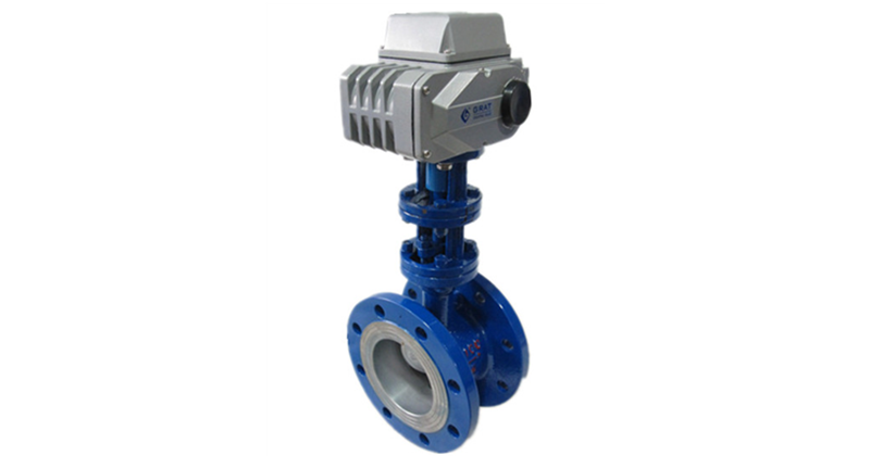
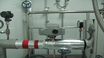
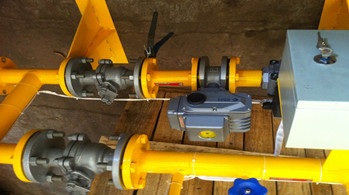
Product Name: Triple Eccentric Electric Butterfly Valve
Product introduction:
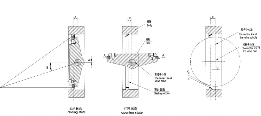
Triple Eccentric Electric Butterfly Valve is with the structure of tri-eccentric conical oblique cutting which sets the center line of flange and the center line of the valve body at an Angle so that the disc leave the sealing surface away from the valve seat sealing surface immediately when open and in the closing moment will touch and press on the valve seat sealing surface.
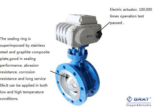
The sealing ring is superimposed by stainless steel and graphite composite plate which can stand the temp. up to 540℃.
It is a device to regulate and cut off the medium of those piping in petroleum chemical power metallurgy and city heat supply system.

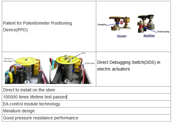
The advantage of configured electric actuator
|
Size (DN) |
DN50~DN1200 |
||||||||
|
Power supply |
AC220V,AC380V,DC24V |
||||||||
|
Body rating(PN) |
PN6 / PN10 / PN16 / PN25 / PN40 |
||||||||
|
Action mode |
Switch on-off / Regulation |
||||||||
|
Control signal |
4-20mA / 0-5V~10V (Optional) |
||||||||
|
Output signal |
4-20mA / 0-5V~10V (Optional) |
||||||||
|
Connection type |
Wafer / Flange |
||||||||
|
Seal type |
Metal seal |
||||||||
|
Test pressure |
Seal |
0.66 |
1.1 |
1.76 |
2.2 |
2.75 |
4.4 |
5.5 |
|
|
Casing |
0.9 |
1.5 |
2.4 |
3.0 |
3.75 |
6.0 |
7.5 |
||
|
Fluid temp. |
≤540℃ |
||||||||
|
Suitable fluid |
Water Oil Gas and various of high temp. or slag inclusion fluid |
||||||||
|
Body material |
WCB、CF8 、CF8M 、CF3M |
||||||||
|
Disc material |
WCB、CF8 、CF8M 、CF3M |
||||||||
|
Seal material |
Stainless steel composite alloy |
||||||||
|
Stuffing |
Soft graphite |
||||||||
|
Protection class |
IP67 |
||||||||
|
Manufacture standard |
GB/T 122381989 、API609 |
||||||||
|
Inspection and test standard |
GB/T 139271992 、API598 |
||||||||
|
Flange standard |
GB9115.88、GB9113.3~5-88、ASME B16.5CL.150,CL.300 and ASME B16.47CL.150 |
||||||||
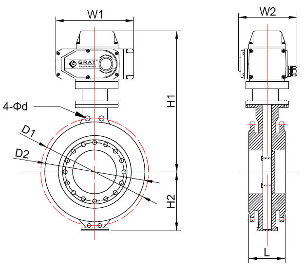
|
Size |
L |
D1 |
D2 |
4-Φd |
H1 |
H2 |
W1 |
W2 |
|
50 |
43 |
125 |
105 |
18 |
238 |
112 |
196 |
145 |
|
65 |
46 |
145 |
125 |
18 |
255 |
115 |
196 |
145 |
|
80 |
56 |
160 |
140 |
18 |
260 |
120 |
196 |
145 |
|
100 |
64 |
180 |
160 |
18 |
285 |
138 |
196 |
145 |
|
125 |
70 |
210 |
190 |
18 |
300 |
164 |
196 |
145 |
|
150 |
71 |
240 |
215 |
22 |
320 |
175 |
255 |
182 |
|
200 |
76 |
295 |
270 |
22 |
370 |
208 |
255 |
182 |
|
250 |
83 |
355 |
325 |
26 |
420 |
243 |
255 |
182 |
|
300 |
92 |
410 |
375 |
26 |
500 |
283 |
255 |
182 |
|
350 |
102 |
470 |
435 |
26 |
530 |
310 |
255 |
182 |
|
400 |
114 |
525 |
545 |
30 |
570 |
340 |
354 |
273 |
|
450 |
127 |
585 |
565 |
30 |
600 |
380 |
354 |
273 |
|
500 |
154 |
650 |
590 |
33 |
680 |
410 |
354 |
273 |
|
600 |
165 |
770 |
690 |
36 |
750 |
470 |
354 |
273 |
|
700 |
190 |
840 |
805 |
36 |
810 |
550 |
354 |
273 |
|
800 |
203 |
950 |
915 |
39 |
905 |
640 |
354 |
273 |
|
900 |
216 |
1050 |
1015 |
39 |
960 |
710 |
354 |
273 |
|
1000 |
254 |
1170 |
1120 |
42 |
1010 |
770 |
354 |
273 |
|
1200 |
265 |
1390 |
1335 |
48 |
1175 |
890 |
354 |
273 |
|
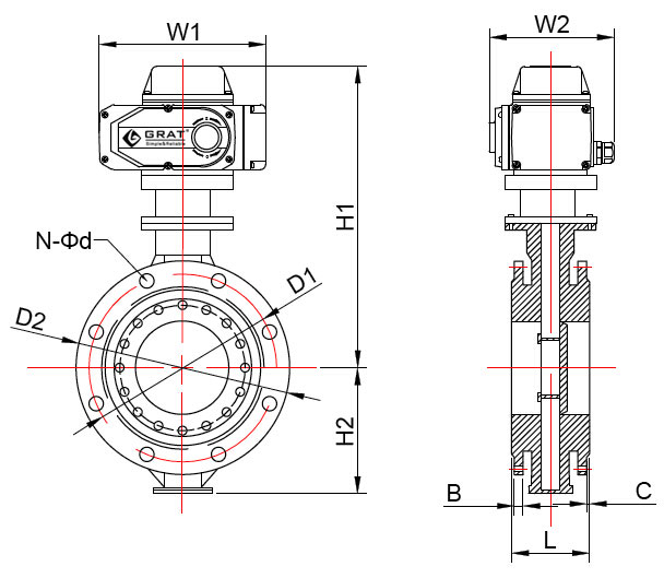
Size |
L |
D1 |
D2 |
n-Φd |
B
|
C
|
H1 |
H2 |
W1 |
W2 |
|
50 |
108
|
125 |
165
|
4-18
|
16
|
2
|
238 |
112 |
196 |
145 |
|
65 |
112
|
145 |
185
|
4-18
|
16
|
2
|
255 |
115 |
196 |
145 |
|
80 |
114
|
160 |
200
|
8-18
|
18
|
2
|
260 |
120 |
196 |
145 |
|
100 |
127
|
180 |
220
|
8-18
|
20
|
3
|
285 |
138 |
196 |
145 |
|
125 |
140
|
210 |
250
|
8-18
|
22
|
3
|
300 |
164 |
196 |
145 |
|
150 |
140
|
240 |
285
|
8-22
|
24
|
3
|
320 |
175 |
255 |
182 |
|
200 |
152
|
295 |
340
|
12-22
|
24
|
3
|
370 |
208 |
255 |
182 |
|
250 |
165
|
355 |
405
|
12-26
|
26
|
3
|
420 |
243 |
255 |
182 |
|
300 |
178
|
410 |
460
|
16-26
|
28
|
3.5
|
500 |
283 |
255 |
182 |
|
350 |
190
|
470 |
520
|
16-30
|
30
|
3.5
|
530 |
310 |
255 |
182 |
|
400 |
216
|
525 |
580
|
20-30
|
32
|
3.5
|
570 |
340 |
354 |
273 |
|
450 |
222
|
585 |
640
|
20-33
|
40
|
3.5
|
600 |
380 |
354 |
273 |
|
500 |
229
|
650 |
715
|
20-36
|
44
|
4
|
680 |
410 |
354 |
273 |
|
600 |
267
|
770 |
840
|
24-36
|
54
|
4
|
750 |
470 |
354 |
273 |
|
700 |
292
|
840 |
910
|
24-39
|
40
|
4
|
810 |
550 |
354 |
273 |
|
800 |
318
|
950 |
1025
|
28-39
|
42
|
4
|
905 |
640 |
354 |
273 |
|
900 |
330
|
1050 |
1125
|
28-42
|
44
|
5
|
960 |
710 |
354 |
273 |
|
1000 |
410
|
1170 |
1255
|
32-48
|
46
|
5
|
1010 |
770 |
354 |
273 |
|
1200 |
470
|
1390 |
1485
|
32-48
|
52
|
5
|
1175 |
890 |
354 |
273 |
|
1300
|
-
|
-
|
-
|
-
|
-
|
-
|
-
|
-
|
-
|
-
|
|
1400
|
530
|
1590
|
1685
|
36-48
|
58
|
5
|
1310
|
860
|
354
|
273
|
|
1500
|
-
|
-
|
-
|
-
|
-
|
-
|
-
|
-
|
-
|
-
|
|
1600
|
600
|
1820
|
1930
|
40-55
|
64
|
5
|
1460
|
980
|
354
|
273
|
|
1800
|
670
|
2020
|
2130
|
44-55
|
68
|
5
|
1560
|
1090
|
354
|
273
|
|
2000
|
-
|
2230
|
2345
|
48-60
|
70
|
5
|
1670
|
1190
|
354
|
273
|

Leading manufacturer of industrial automation equipment
 HOME
HOME
 Tel:400-027-3353
 Fax:027-60706976/60706977
 Email: ft@grat.com.cn
  Web:en.grat.com.cn

 Electric actuator


 Tel:400-027-3353
 Fax:027-60706976/60706977
 Skype:grat2015@outlook.com
 Email:
 Add:B8-3-2, OVU,Wuhan,Hubei,China.