

|
Supply power |
AC220V 50/60HZ |
|
Inside nominal diameter |
DN15-200 |
|
Medium temp. |
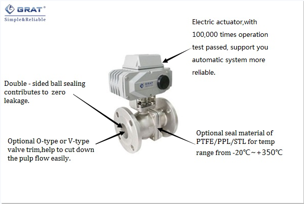
-20℃ ~ 350℃ (200℃ special seal material) |
|
Nominal pressure |
PN16 PN25,PN40,PN64,PN100 |
|
Input signal |
4-20mA |
|
Output signal |
4-20mA |
|
Connection type |
Flange |
|
Body material |
A105、F304、F316、WCB、FZG1Cr18Ni9Ti、ZG1Cr18Ni12Mo2Ti、CF8、CF8M、CF3M |
|
Valve seat material |
PTFE(Normal temp.)、PPL(Medium temp.)、Metal seat(High temp.) |
|
Leakage level |
ANSIB16.104 5 |
|
Seal type |
Elastic seal、PPL 、STL、Ceramic |
|
Suitable medium |
Water、Oil、Nitric acid、Acetic acid、Viscous fluid、Pulp、Oxidant |
|
Protection class |
IP67 |
|
Manufacture standard |
JB/T8692-1998 |
|
Length standard |
GB1221-89 |
|
Inspection standard |
JB/T 9092 API598 |
|
Size |
DN | 15 | 20 | 25 | 32 | 40 | 50 | 65 | 80 | 100 | 125 | 150 | 200 |
| inch | 0.5" | 0.75" | 1" | 1.25" | 1.5" | 2" | 2.5" | 3" | 4" | 5" | 6" | 8" | |
|
CV value |
18 | 36 | 48 | 93 | 165 | 207 | 450 | 780 | 1360 | 1700 | 2600 | 4200 | |
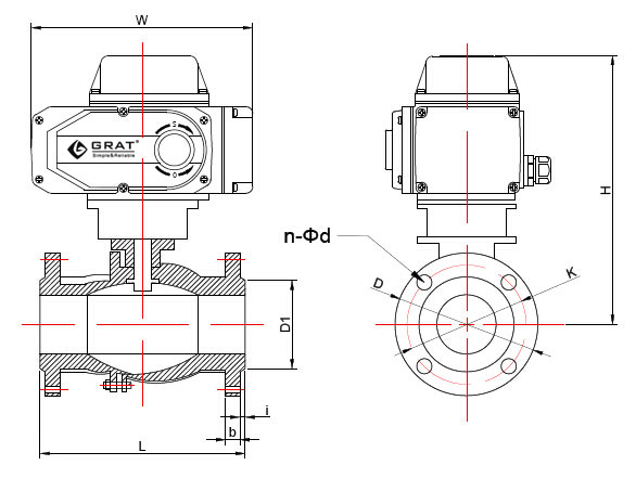
Standard of CNS
Design standard:GB/T12237-2007
Flange standard:HG/T20592 Unit:(mm)
|
(DN) |
L |
D |
K |
D1 |
n-Φd |
b |
i |
H |
W |
|
|
mm |
in |
|||||||||
|
15 |
1/2″ |
130 |
95 |
65 |
45 |
4-14 |
14 |
2 |
209 |
196 |
|
20 |
3/4″ |
130 |
105 |
75 |
55 |
4-14 |
16 |
2 |
211 |
196 |
|
25 |
1″ |
142 |
113 |
85 |
65 |
4-14 |
18 |
2 |
218.5 |
196 |
|
32 |
1-1/4″ |
165 |
140 |
100 |
78 |
4-18 |
18 |
2 |
233 |
196 |
|
40 |
1-1/2″ |
165 |
150 |
110 |
85 |
4-18 |
18 |
2 |
234 |
196 |
|
50 |
2″ |
203 |
165 |
125 |
100 |
4-18 |
20 |
2 |
248 |
196 |
|
65 |
2-1/2″ |
222 |
185 |
145 |
120 |
8-18 |
20 |
2 |
294 |
255 |
|
80 |
3″ |
241 |
200 |
160 |
135 |
8-18 |
21 |
2 |
320 |
255 |
|
100 |
4″ |
305 |
220 |
180 |
155 |
8-18 |
22 |
2 |
339 |
255 |
|
125 |
5″ |
356 |
250 |
210 |
184 |
8-18 |
22 |
3 |
392 |
255 |
|
150 |
6″ |
394 |
285 |
240 |
210 |
8-23 |
24 |
3 |
402 |
255 |
|
200 |
8″ |
457 |
340 |
295 |
265 |
12-23 |
26 |
3 |
467 |
255 |
Standard of JIS
Design standard:API B2002
Flange standard:JIS B2220-2004 Unit:(mm)
|
|
L |
D |
K |
D1 |
b |
i |
n-Φd |
H |
W |
|
15 |
108 |
95 |
70 |
51 |
12 |
2 |
4-15 |
209 |
196 |
|
20 |
117 |
100 |
75 |
56 |
14 |
2 |
4-15 |
213 |
196 |
|
25 |
127 |
125 |
90 |
67 |
14 |
2 |
4-19 |
221 |
196 |
|
32 |
140 |
135 |
100 |
76 |
16 |
2 |
4-19 |
229 |
196 |
|
40 |
165 |
140 |
105 |
81 |
16 |
2 |
4-19 |
239 |
196 |
|
50 |
178 |
155 |
120 |
96 |
16 |
2 |
4-19 |
246 |
196 |
|
65 |
190 |
175 |
140 |
116 |
18 |
2 |
4-19 |
306 |
255 |
|
80 |
203 |
185 |
150 |
126 |
18 |
2 |
8-19 |
316 |
255 |
|
100 |
229 |
210 |
175 |
151 |
18 |
2 |
8-19 |
339 |
255 |
|
125 |
356 |
250 |
210 |
182 |
20 |
2 |
8-23 |
371 |
255 |
|
150 |
394 |
280 |
240 |
212 |
20 |
2 |
8-23 |
399 |
255 |
|
200 |
457 |
330 |
290 |
262 |
20 |
2 |
12-23 |
438 |
255 |
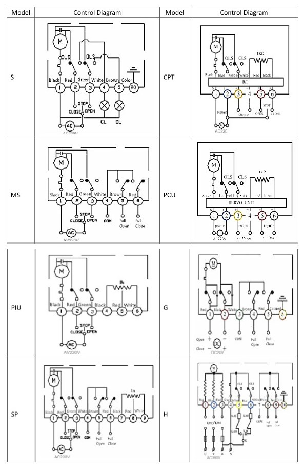
| Model | Circuit | Model | Circuit |
| S | ON/OFFno output signal | CPT | ON/OFFoutput 4~20mA signal |
| MS | ON/OFFoutput passive contact signal | PCU | Regulationoutput 4~20mA signal |
| PIU | ON/OFFoutput 0~1000Ω signal | G | ON/OFFoutput passive contact signal |
| SP | ON/OFFmiddle position control | H | ON/OFFoutput passive contact signal |
Leading manufacturer of industrial automation equipment
 HOME
HOME
 Tel:400-027-3353
 Fax:027-60706976/60706977
 Email: ft@grat.com.cn
  Web:en.grat.com.cn

 Electric actuator


 Tel:400-027-3353
 Fax:027-60706976/60706977
 Skype:grat2015@outlook.com
 Email:
 Add:B8-3-2, OVU,Wuhan,Hubei,China.