

Category: Electric ball valve
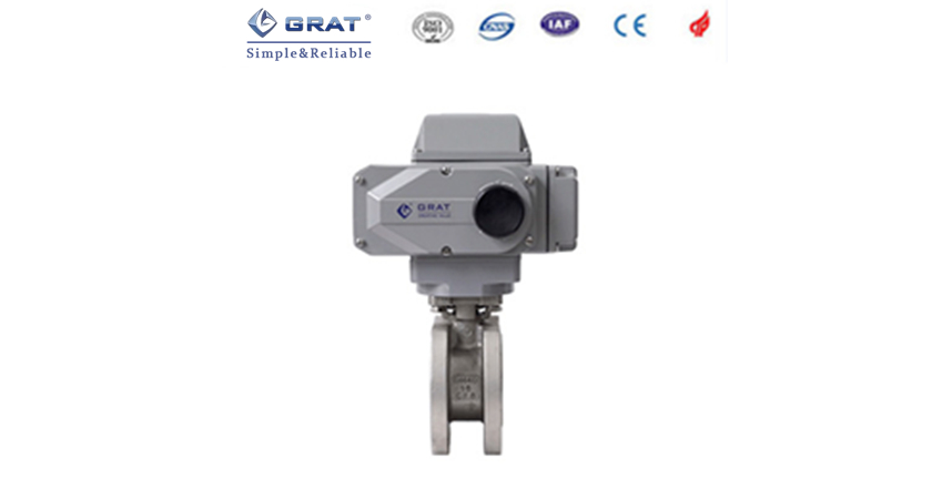
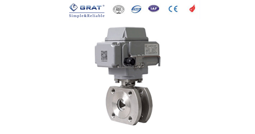
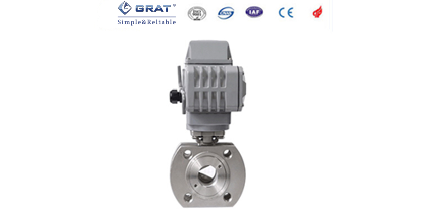
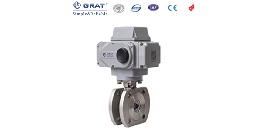
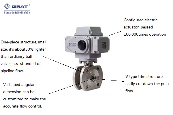
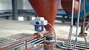
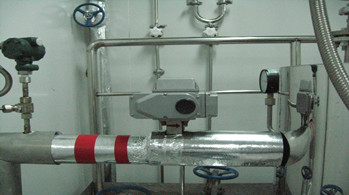
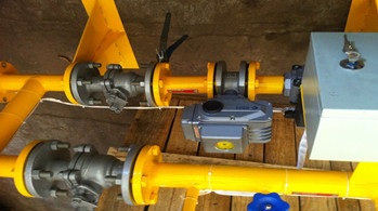
Product Name: Electric V-notch Cut Ball Valve
Product introduction:
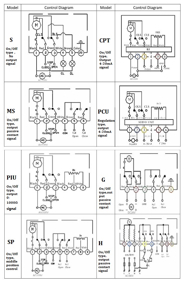
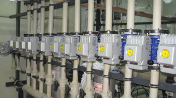
Electric V-notch Cut ball valve configured with the intelligent actuator which can make the proportional control receives the ON - OFF or 20 MAC or 1-4-5 VDC signal from high precision electric actuators and indicates the angle of direct instruction and feedback. The switch type product can operate only by the single-phase power to make the parameters regulation including pressure flow temperature the level of liquid and so on.
The V-notch cut in disc can rotate reversely & correspondingly with metal seal to produce shear force to cut off fibre and prevent the block. This valve is special suitable for mud and fibrous media and suspended solids containing minimal media.

|
Nominal diameter
DN(mm) |
15
|
20
|
25
|
32
|
40
|
50
|
65
|
80
|
100
|
125
|
150
|
200
|
|
|
100% opening CV data
|
O type
|
24
|
44
|
84
|
122
|
198
|
320
|
443
|
595
|
1096
|
1692
|
2602
|
4212
|
|
Rectangle
|
8.7
|
13.4
|
20
|
32.6
|
44.3
|
70
|
114
|
134
|
186
|
270
|
462
|
688
|
|
|
V type
|
7.5
|
11
|
17
|
28
|
38
|
60
|
98
|
116
|
155
|
233
|
397
|
595
|
|
|
Flow characteristics
|
Rectangle:Linear; V type(logarithm)Eq%; O type:Switch on-off
|
||||||||||||
| Rangeability | 50:1 100:1 300:1 | ||||||||||||
| Nominal diameter | DN15-DN200(Write to us for more details for >DN200) | ||||||||||||
|
Nominal pressure
|
PN1.6~6.4MPa
|
||||||||||||
|
Connection type
|
Flange, Thread
|
||||||||||||
|
Action time
|
15S 30S (Optional )(0-90°)
|
||||||||||||
| Power supply | AC220V AC380V DC24V | ||||||||||||
| Control signal | 4~20mA 0~5V | ||||||||||||
| Output signal | 4~20mA 0~5V | ||||||||||||
| Medium temp. | ≤220℃ | ||||||||||||
| Ambient temp. | ≤50℃ | ||||||||||||
| Suited medium | Food Lubricating grease Fibrous liquid | ||||||||||||
| Dead band | 0.5% | ||||||||||||
| Repeatable error | 0.5% | ||||||||||||
|
Body material
|
WCB(ZG230-450)、Stainless steel(ZG1Cr18Ni9Ti、316、316L)
|
||||||||||||
|
Trim material
|
Stainless steel(ZG1Cr18Ni9Ti、316、316L、A105、304)etc
|
||||||||||||
|
Stem material
|
Stainless steel(ZG1Cr18Ni9Ti、316、316L)
|
||||||||||||
|
Stuffing material
|
PTFE Soft graphit
|
||||||||||||
|
Seal type
|
Soft seal
|
||||||||||||
|
Valve seat
|
PTFE
|
Carbon fiber PTFE
|
|||||||||||
|
Leakage
|
Ⅵ class
|
||||||||||||
| Medium temp. | N:-40℃-180℃ | M:-40℃-280℃ | |||||||||||
| Manufacture standard | GB/T 122387-89 | ||||||||||||
| Flange standard | GB9113-2000、GB17241.6-1998 | ||||||||||||
| Length standard | GB1221-89 | ||||||||||||
| Inspection standard | GB/T 13927-92 | ||||||||||||
|
Size |
DN | 25 | 32 | 40 | 50 | 65 | 80 | 100 | 125 | 150 | 200 | 250 | 300 | 350 | 400 | 450 | 500 |
| inch | 1" | 1.25" | 1.5" | 2" | 2.5" | 3" | 4" | 5" | 6" | 8" | 10" | 12" | 14" | 16" | 18" | 20" | |
| CV data | 36 | 56 | 94 | 152 | 262 | 358 | 540 | 906 | 1424 | 2176 | 3532 | 5732 | 8245 | 10651 | 12878 | 16343 | |
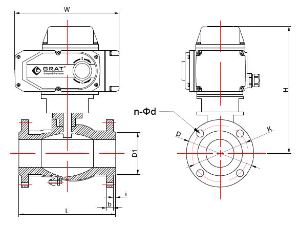
CNS Standard size of Short flange
Design standard:GB/T12237-2007
Flange standard:GB/T9113-2010 Unit:(mm)
|
Nominal diameter |
d
|
D1
|
K
|
D
|
n-Md
|
f
|
L
|
H
|
W
|
|
|
DN15
|
1/2〃
|
15
|
45
|
65
|
95
|
4-M12
|
2
|
35
|
210
|
196
|
|
DN20
|
3/4〃
|
19
|
55
|
75
|
105
|
4-M12
|
2
|
38
|
216
|
196
|
|
DN25
|
1〃
|
25
|
65
|
85
|
115
|
4-M12
|
2
|
50
|
223
|
196
|
|
DN32
|
1-1/4〃
|
28
|
76
|
100
|
140
|
4-M12
|
2
|
50
|
230
|
196
|
|
DN40
|
1-1/2〃
|
38
|
83
|
110
|
148
|
4-M16
|
3
|
67
|
240
|
196
|
|
DN50
|
2〃
|
49
|
102
|
125
|
156
|
4-M16
|
3
|
72
|
250
|
196
|
|
DN65
|
2-1/2〃
|
64
|
120
|
145
|
185
|
4-M16
|
3
|
94
|
298
|
255
|
|
DN80
|
3〃
|
73
|
143
|
160
|
200
|
8-M16
|
3
|
120
|
312
|
255
|
|
DN100
|
4〃
|
90
|
168
|
180
|
220
|
8-M16
|
3
|
141
|
322
|
255
|
|
DN125
|
5〃
|
110
|
185
|
210
|
245
|
8-M16
|
3
|
165
|
397
|
255
|
|
DN150
|
6〃
|
145
|
208
|
240
|
277
|
8-M20
|
3
|
225
|
422
|
255
|
|
DN200
|
8〃
|
195
|
265
|
395
|
335
|
12-M20
|
3
|
275
|
512
|
255
|
DIN Standard size of Short flange
Design standard:DIN3375/1,2,EN12516-1
Flange standard:DIN EN1092-1 PN10-PN40 Unit:(mm)
|
Nominal diameter |
d
|
D1
|
K
|
D
|
n-Md
|
f
|
L
|
H
|
W
|
|
|
DN15
|
1/2〃
|
15
|
45
|
65
|
95
|
4-M12
|
2
|
44
|
220
|
196
|
|
DN20
|
3/4〃
|
20
|
58
|
75
|
105
|
4-M12
|
2
|
44
|
220
|
196
|
|
DN25
|
1〃
|
25
|
68
|
85
|
115
|
4-M12
|
2
|
50
|
223
|
196
|
|
DN32
|
1-1/4〃
|
32
|
78
|
100
|
140
|
4-M16
|
2
|
60
|
237
|
196
|
|
DN40
|
1-1/2〃
|
38
|
88
|
110
|
150
|
4-M16
|
3
|
65
|
244
|
196
|
|
DN50
|
2〃
|
49
|
102
|
125
|
165
|
4-M16
|
3
|
80
|
245
|
196
|
|
DN65
|
2-1/2〃
|
62
|
122
|
145
|
185
|
4-M16
|
3
|
110
|
306
|
255
|
|
DN80
|
3〃
|
74
|
138
|
160
|
200
|
8-M16
|
3
|
120
|
326
|
255
|
|
DN100
|
4〃
|
100
|
158
|
180
|
220
|
8-M16
|
3
|
152
|
338
|
255
|
|
DN125
|
5〃
|
118
|
188
|
210
|
250
|
8-M16
|
3
|
180
|
363
|
255
|
|
DN150
|
6〃
|
150
|
212
|
240
|
285
|
8-M20
|
3
|
232
|
396.5
|
255
|
CNS Standard size of long flange
Design standard:GB/T12237-2007
Flange standard:HG/T20592 Unit:(mm)
|
Nominal diameter
|
L
|
D
|
K
|
D1
|
n-Φd
|
b
|
i
|
H
|
W
|
|
|
mm
|
in
|
|||||||||
|
15
|
1/2″
|
130
|
95
|
65
|
45
|
4-14
|
14
|
2
|
209
|
196
|
|
20
|
3/4″
|
130
|
105
|
75
|
55
|
4-14
|
16
|
2
|
211
|
196
|
|
25
|
1″
|
142
|
113
|
85
|
65
|
4-14
|
18
|
2
|
218.5
|
196
|
|
32
|
1-1/4″
|
165
|
140
|
100
|
78
|
4-18
|
18
|
2
|
233
|
196
|
|
40
|
1-1/2″
|
165
|
150
|
110
|
85
|
4-18
|
18
|
2
|
234
|
196
|
|
50
|
2″
|
203
|
165
|
125
|
100
|
4-18
|
20
|
2
|
248
|
196
|
|
65
|
2-1/2″
|
222
|
185
|
145
|
120
|
8-18
|
20
|
2
|
294
|
255
|
|
80
|
3″
|
241
|
200
|
160
|
135
|
8-18
|
21
|
2
|
320
|
255
|
|
100
|
4″
|
305
|
220
|
180
|
155
|
8-18
|
22
|
2
|
339
|
255
|
|
125
|
5″
|
356
|
250
|
210
|
184
|
8-18
|
22
|
3
|
392
|
255
|
|
150
|
6″
|
394
|
285
|
240
|
210
|
8-23
|
24
|
3
|
402
|
255
|
|
200
|
8″
|
457
|
340
|
295
|
265
|
12-23
|
26
|
3
|
467
|
255
|

Leading manufacturer of industrial automation equipment
 HOME
HOME
 Tel:400-027-3353
 Fax:027-60706976/60706977
 Email: ft@grat.com.cn
  Web:en.grat.com.cn

 Electric actuator


 Tel:400-027-3353
 Fax:027-60706976/60706977
 Skype:grat2015@outlook.com
 Email:
 Add:B8-3-2, OVU,Wuhan,Hubei,China.