

Category : Electric Ball Valve
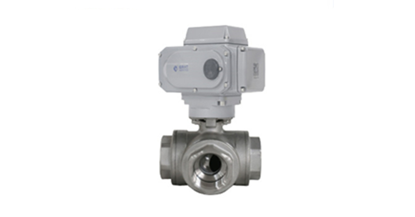
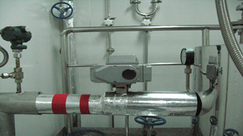
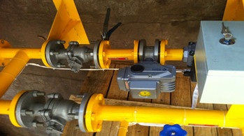
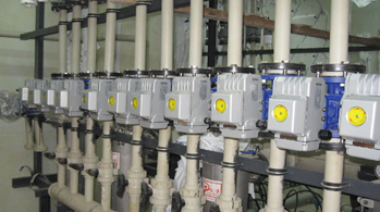
Product Name: Electric 3 way Ball Valve
Product introduction:

|
Diameter |
DN15~200 |
|
Power Supply |
DC24V、AC110、AC220V |
|
Actuator Material |
Cast alumimium alloy |
|
Medium Temp. |
0~120℃ |
|
Ambient Temp. |
-30℃-60℃ |
|
Nominal Pressure |
0.1~6.4MPa |
|
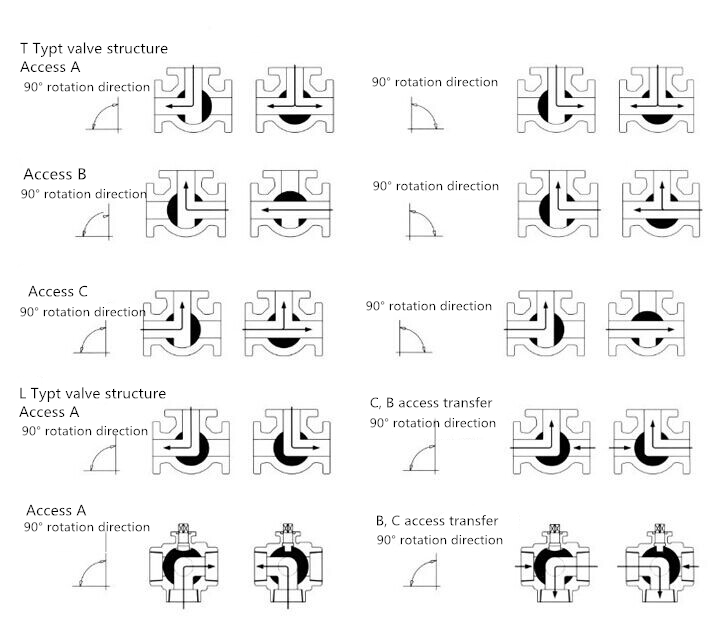
Motion Action |
Switch On/Off (shunt & confluence) |
|
Action Time |
4-30S |
|
Suitable Working Conditions |
Air-con、Fire extingushing system、Water processing sysem 、Pipeline purging 、Analysis Instruments、Flue-gas sampling |
|
Connection |
Female screw thread Flange |
|
Seal Form |
Soft seal |
|
Body Material |
SUS304、SUS316,WCB |
|
Seal Ring Material |
EPDM、PTFE |
|
Protection Class |
IP67 |
|
Installation Angle |
Insallation in any orientation |
|
Manufactoring Standard |
GB12237-89 AP16D |
|
Flange Standard |
GB9113-2000、GB17241.6-1998 |
|
Length Standard |
GB12221-89 |
|
Implementation Standard |
JB/T 9092 API598 |
1、Thread Connection Drawing
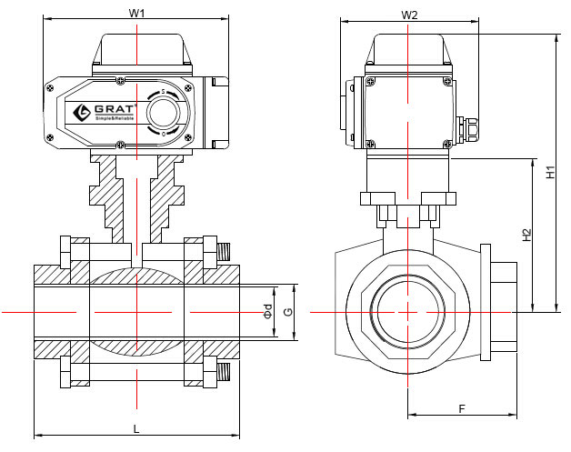
Design Standard:Mss sp-110
Thread Standard:ASME B1.20.1,BS21
DIN 2999/259,ISO 228/1
JIS B 0203,ISO 7/1 Unit:(mm)
|
Diameter |
L |
G |
Φd |
F |
H1 |
H2 |
W1 |
W2 |
|
12 |
70 |
Thread Standard: BSP DIN etc |
12 |
40 |
196 |
38 |
196 |
145 |
|
15 |
83 |
15 |
42 |
198 |
40 |
196 |
145 |
|
|
18 |
89 |
18 |
54 |
208 |
50 |
196 |
145 |
|
|
25 |
116 |
25 |
60 |
217 |
59 |
196 |
145 |
|
|
32 |
134 |
32 |
68 |
228 |
70 |
196 |
145 |
|
|
38 |
152 |
38 |
84 |
232 |
74 |
196 |
145 |
|
|
50 |
200 |
50 |
98 |
251 |
93 |
196 |
145 |
|
|
65 |
240 |
65 |
106 |
302 |
110 |
255 |
182 |
|
|
80 |
278 |
80 |
114 |
325 |
133 |
255 |
182 |
2、Flange Connection Drawing
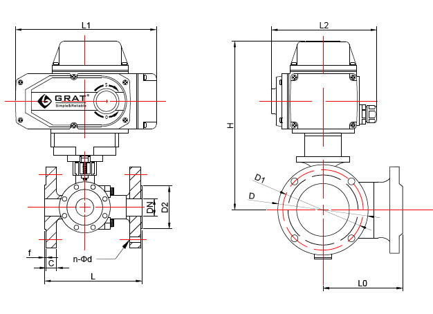
Design Standard:GB/T12237-2007
Flange Standard:HG/T20592 Unit:(mm)
|
Diameter |
L |
L0 |
D2 |
C |
f |
D |
D1 |
H |
n-Φd |
L1 |
L2 |
|
15 |
150 |
75 |
45 |
14 |
2 |
95 |
65 |
216 |
4-14 |
196 |
145 |
|
20 |
160 |
80 |
55 |
14 |
2 |
105 |
75 |
230 |
4-14 |
196 |
145 |
|
25 |
180 |
90 |
65 |
14 |
2 |
115 |
85 |
236 |
4-14 |
196 |
145 |
|
32 |
200 |
100 |
78 |
16 |
2 |
135 |
100 |
245 |
4-18 |
196 |
145 |
|
40 |
220 |
110 |
85 |
16 |
3 |
145 |
110 |
258 |
4-18 |
196 |
145 |
|
50 |
240 |
120 |
100 |
16 |
3 |
160 |
125 |
264 |
4-18 |
196 |
145 |
|
65 |
260 |
130 |
120 |
16 |
3 |
180 |
145 |
302 |
4-18 |
255 |
182 |
|
80 |
280 |
140 |
135 |
18 |
3 |
195 |
160 |
310 |
8-18 |
255 |
182 |
|
100 |
320 |
160 |
155 |
20 |
3 |
215 |
180 |
320 |
8-18 |
255 |
182 |
Leading manufacturer of industrial automation equipment
 HOME
HOME
 Tel:400-027-3353
 Fax:027-60706976/60706977
 Email: ft@grat.com.cn
  Web:en.grat.com.cn

 Electric actuator


 Tel:400-027-3353
 Fax:027-60706976/60706977
 Skype:grat2015@outlook.com
 Email:
 Add:B8-3-2, OVU,Wuhan,Hubei,China.